David Nelson's Web Site

|
David Nelson's Web Site
|
|
|
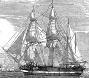
HMS Terror The HMS Terror and HMS Erebus were the two ships the British Navy sent out in 1845 to find the Northwest Passage across the Arctic with the objective of having a shorter trip from the Atlantic to the Pacific. This expedition was and is best known as the Franklin Expedition. The ships were almost identical and had been involved with explorations previously. For the Franklin Expedition a number of changes were made.
The model To prepare for this model I obtained plans for both the Erebus and the Terror from the National Maritime Museum in Greenwich. The much research was done to gather more information and details about the ships. It turned out the there was more information in books and on the Internet about the Terror so I decided to model it.
October 16, 2023
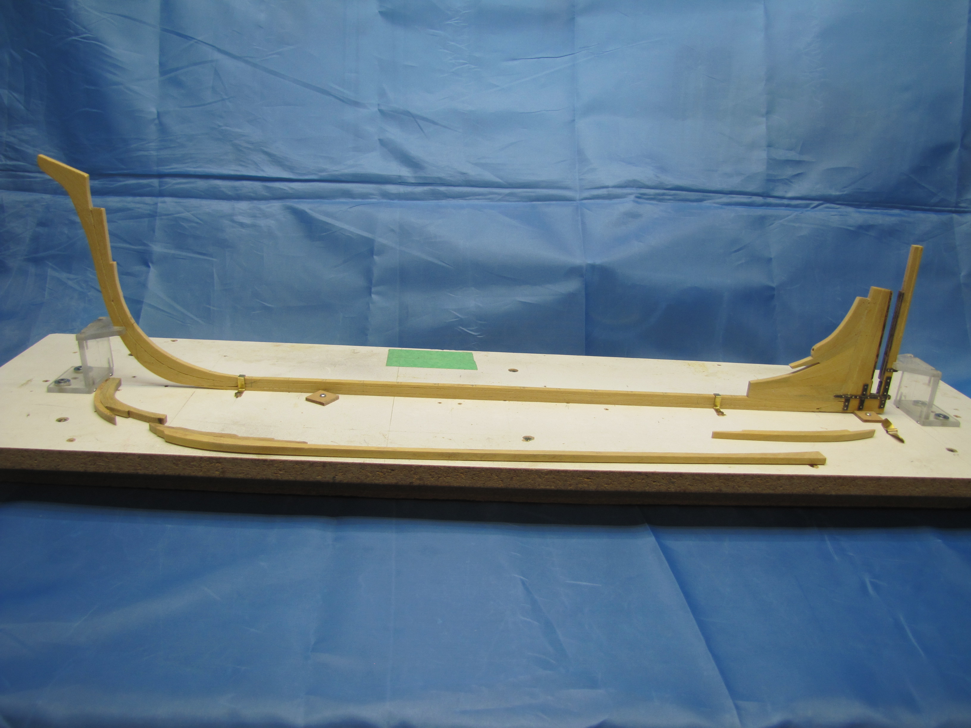
Keel, stem and stern posts mounted on the building
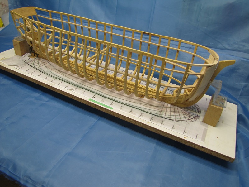
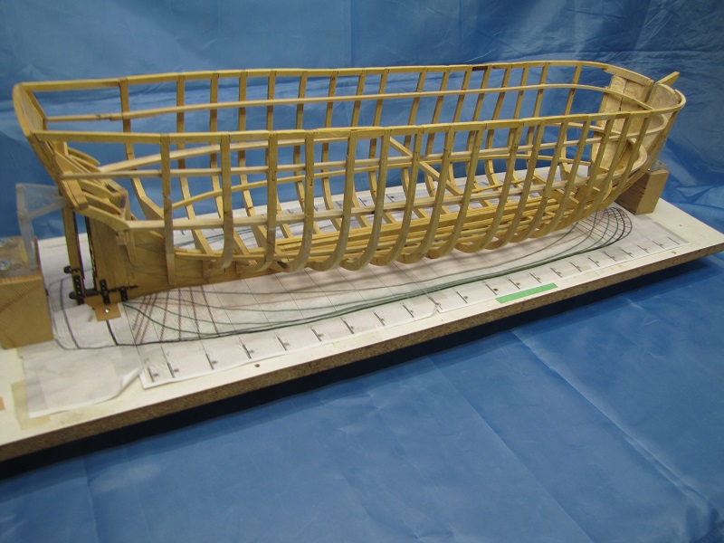
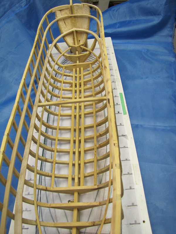
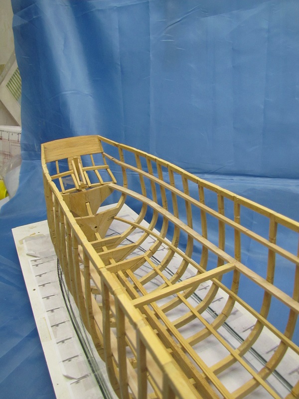
board. The keelson and other timber laying January 30/24 The framing of the model is now in place. Next comes the inner and outer planking.
View of the models framing from the front quarter.
View from the rear quarter.
Framing interior looking towards the bow. The
upper three beams running the length of the model
Framing interior looking aft. Note the hole in
the bulkhead. It is for the shaft that will February 29, 2024
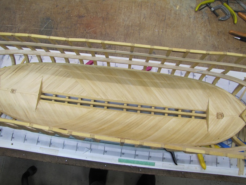
The hold planking seen here is partially complete. It is double planked with the planks laid at 45 degrees from the keel and the two layers of planking at 90 degrees to each other. In this picture the forward portion has the second layer of planking while the aft part only has one.
August 9, 2024 The outer planking as far up as the lower deck is
complete. Before this is taken any
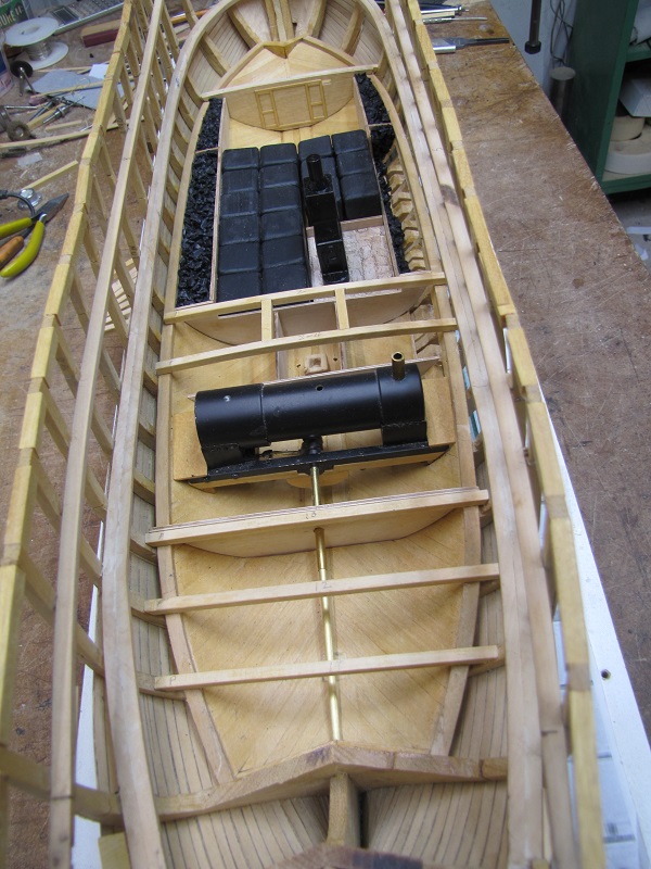
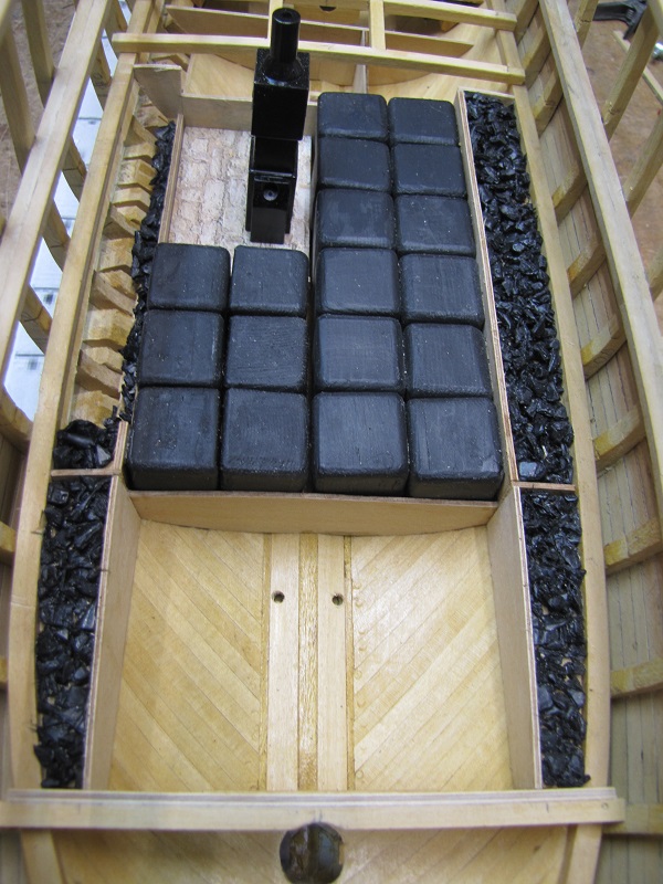
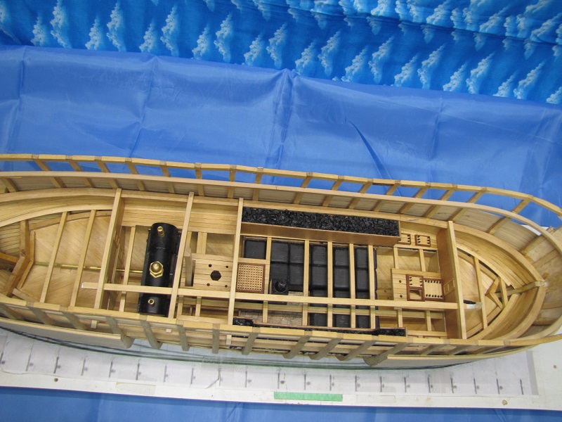
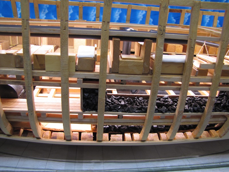
The hold looking forward. The engine and drive
shaft are seen in the bottom of the
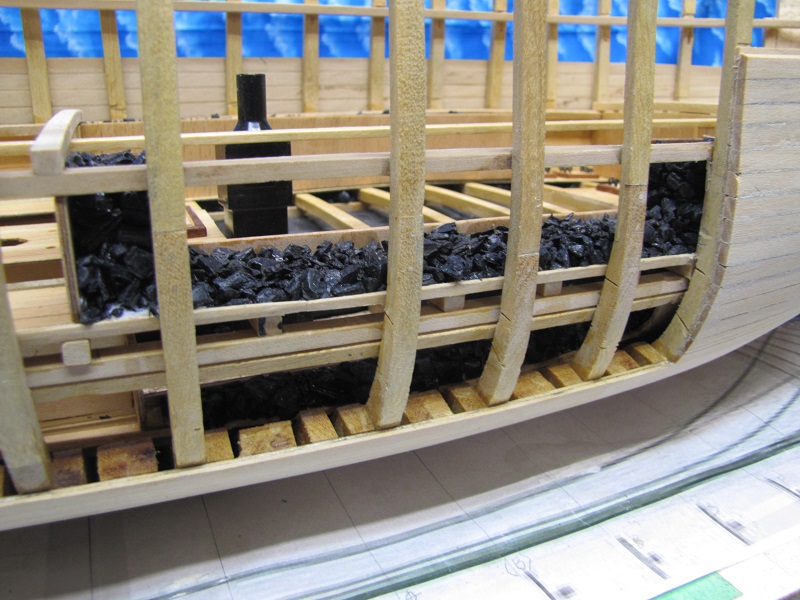
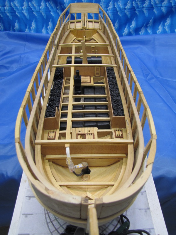
Looking aft from the bow we get a better view of the coal compartments and the furnace. September 29, 2024 The orlop deck is now complete.
Here we see the finished orlop deck. From the
left we have the locomotive, the spare rudder
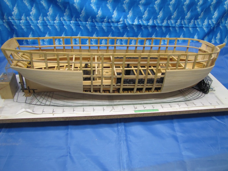
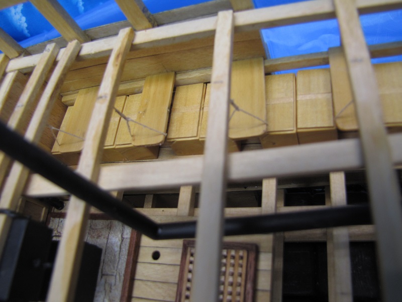
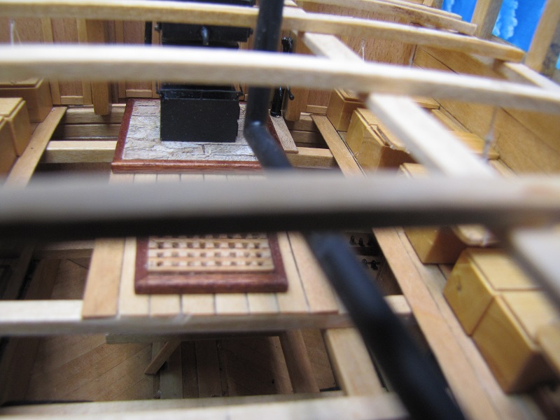
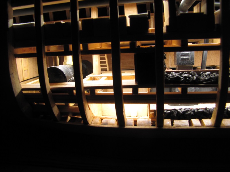
View of the interior visible through the area of the
hull that will remain unplanked. The
The unplanked portion of the hull.
Looking down the deck from the bow. The wiring at
the bow is strip lighting that will
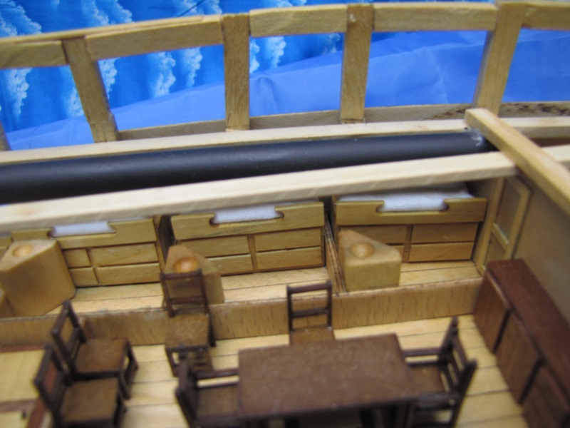
November 25, 2024 The lower deck, which contains the crews quarters and galley, is now complete.
Senior officers sleeping quarters. They provide a
bed with drawers below for personal belongings and
Seamen's mess area. Tables are suspended from the
deck beams. The chests below the tables act as seats and
In the top/center of this picture we see the galley
stove and next to it a pump used to bring fresh water from
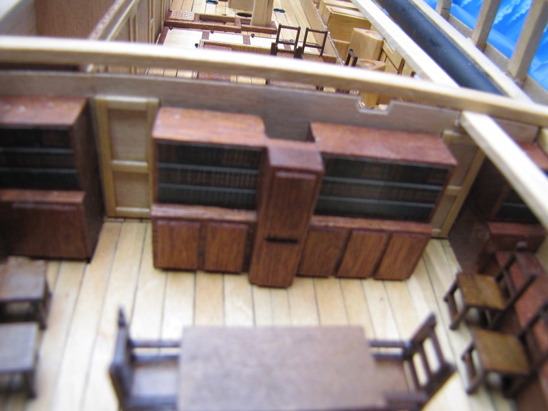
Book cases and cabinets in the captain's quarters.
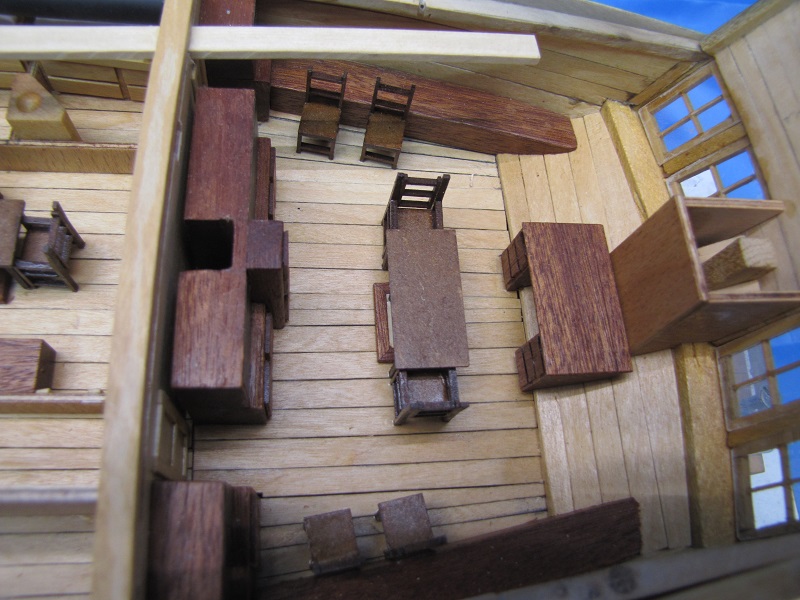
The captain's quarters.
View of the interior through the open side of the hull with interior lighting on.
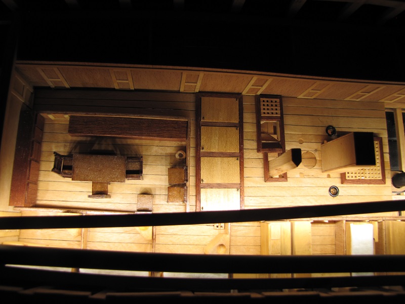
Looking at the lighted deck.
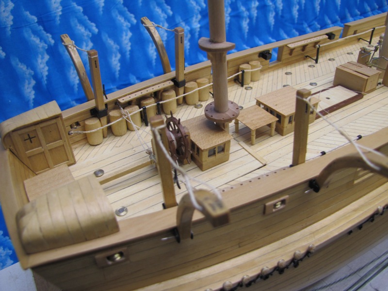
The lighted interior. May 31 2025 The upper deck is now complete with all of it's fittings.
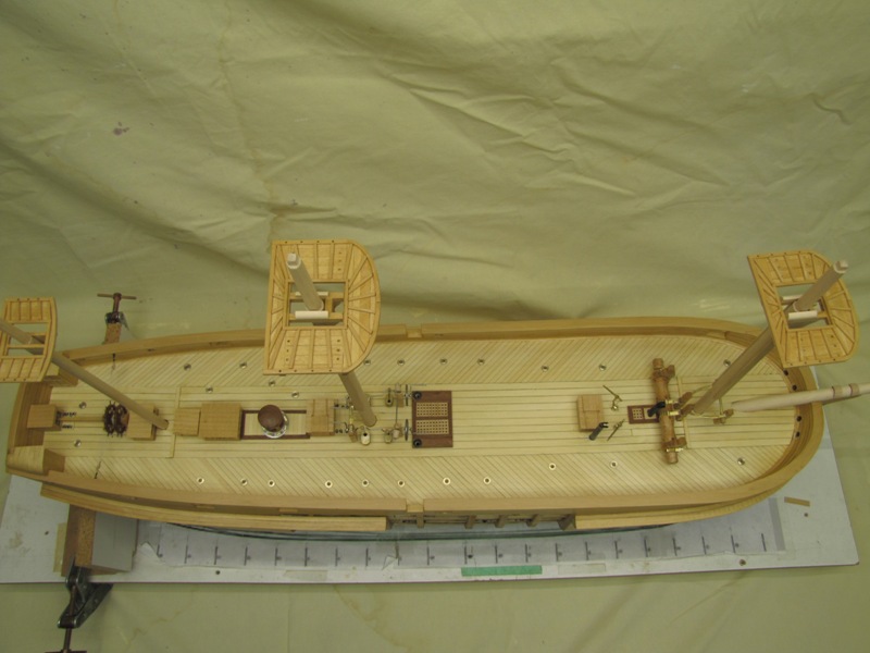
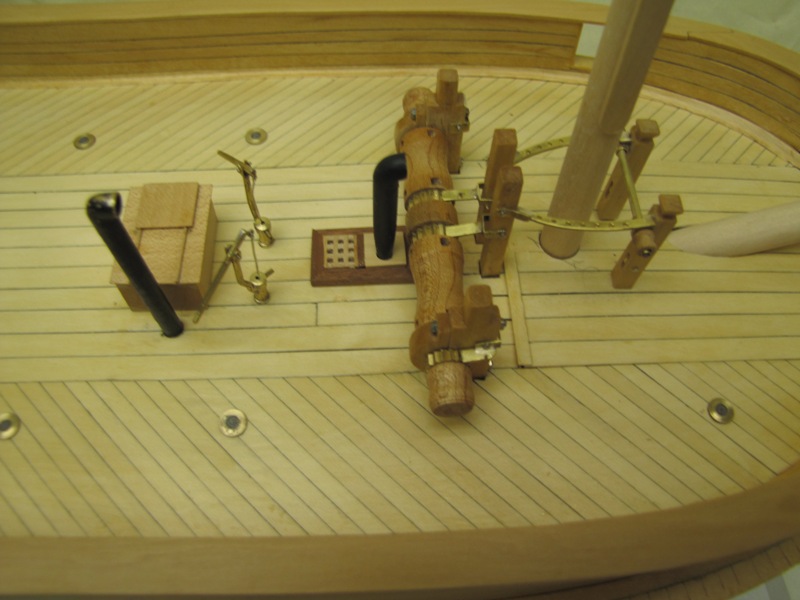
View of the deck from above. The lower masts and
bowsprit are sitting in place but not yet fastened in.
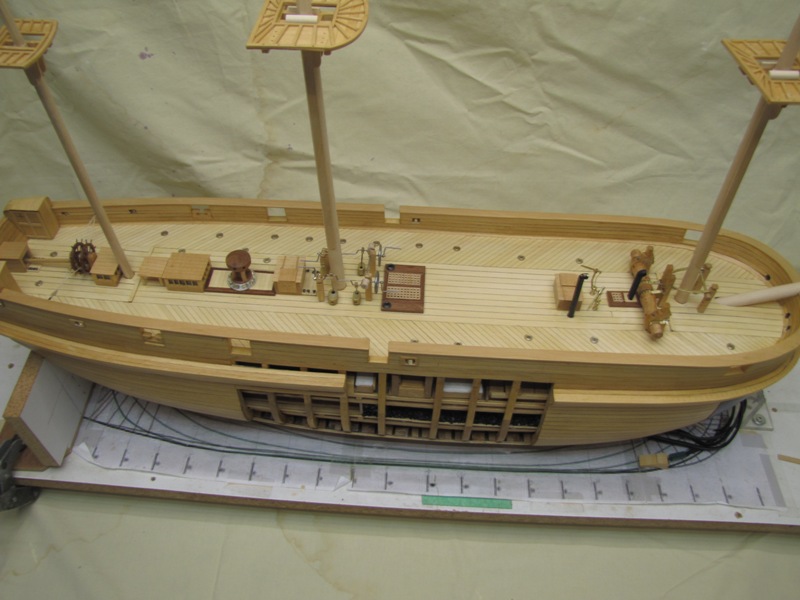
Another view of the deck.
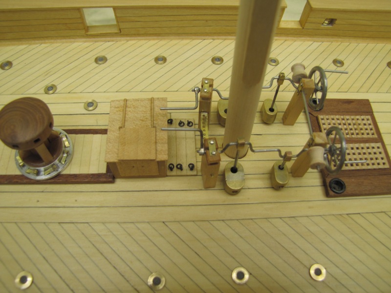
The center of the deck showing from the right.
The main hatch, Massey's patent pumps, main mast, scuttle
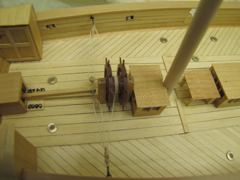
The fore deck showing the foot of the bowsprit, winch,
pin rails, fore mast, windless, chimney for the galley
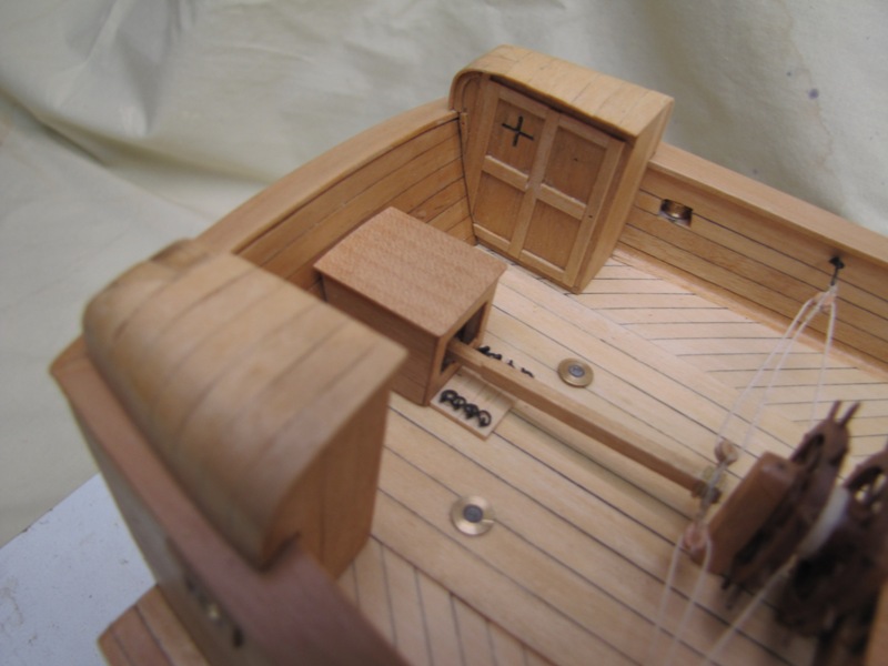
The aft deck. Here we have the skylight for the
officers mess, table for the azimuth compass, Mizzen mast,
The water closets.
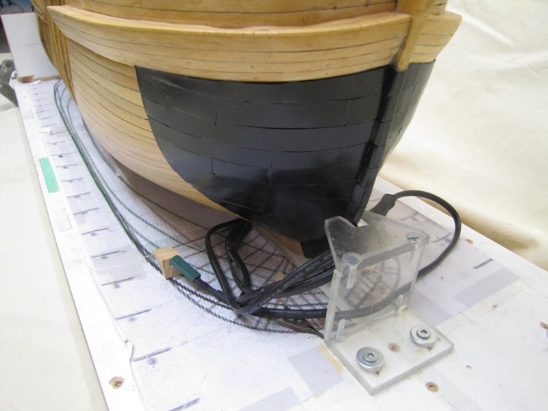
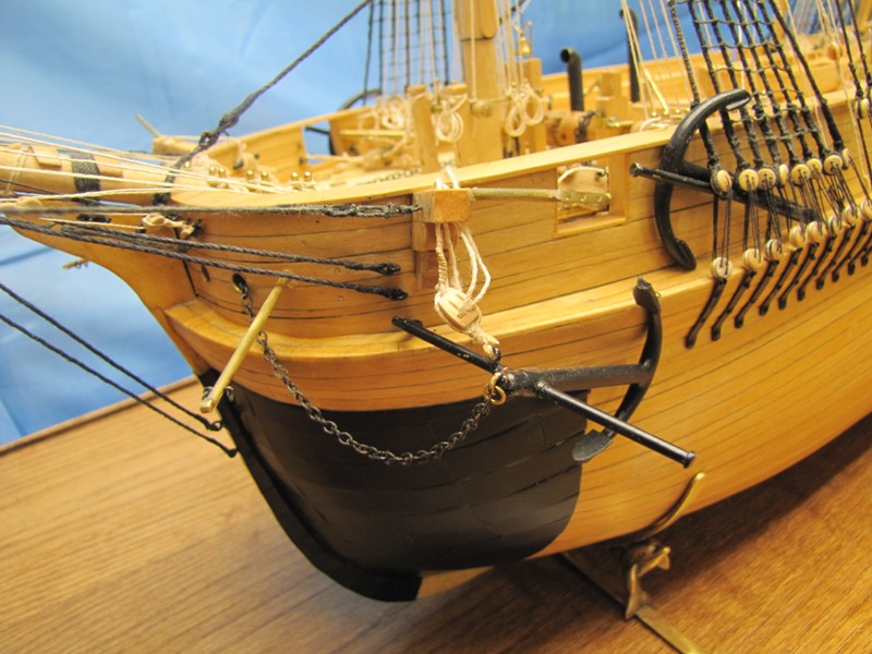
The metal plates installed to protect the bow from the
ice. The wires we see here are for the interior lighting. July 29, 2025 The statement at the start of the May update saying the
upper deck fittings were complete was a little
Here we have the side davits from which a cutter will
be suspended. Along the port gunwale is storage
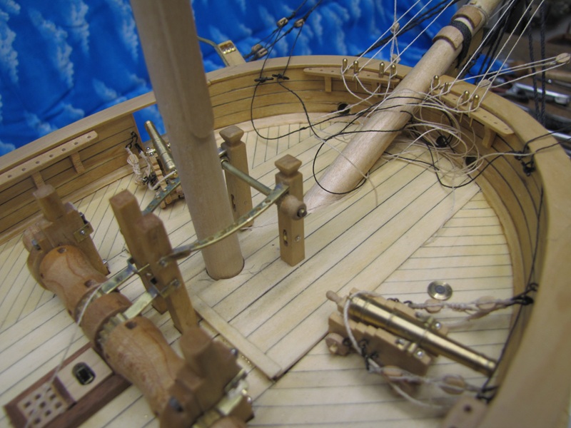
In this image we see the two ships cannon, the inner
portion of the bowsprit and pin rails for rigging from
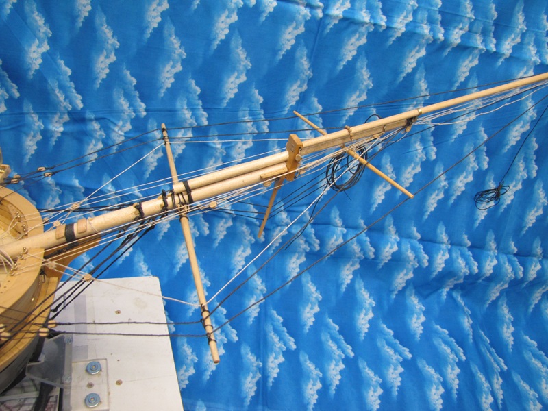
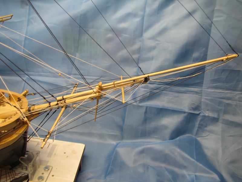
Rigging of the bowsprit, jib boom, sprit sail and sprit topsail yards. When research into the Terror's rigging was started it
was clear the no specific information was available
This image includes the flying job boom. The coiled lines are the jib and flying jib stays.
Here we have the bob stays, shrouds and guys where they fasten to the hull.
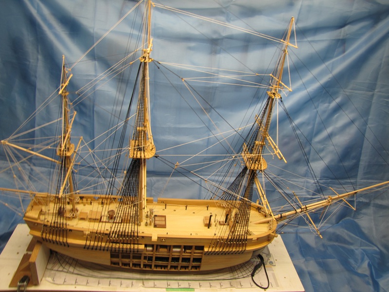
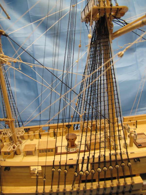
January 17, 2029 The rigging on the model is now complete which add significantly to the model's appearance.
Profile of the Terror showing the completed rigging.
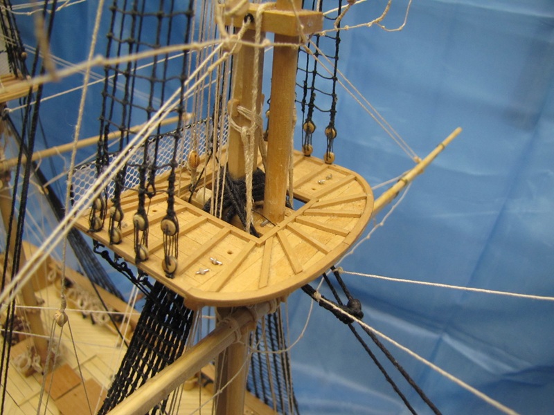
The main top.
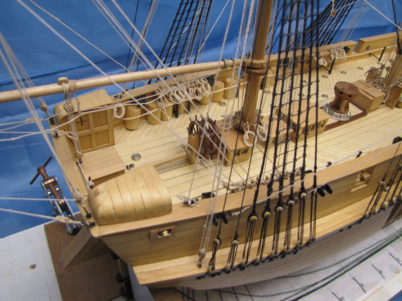
Aft portion of the deck.
Lower shrouds and backstays of the main mast.
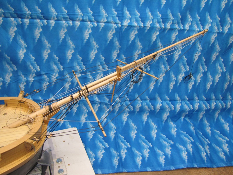
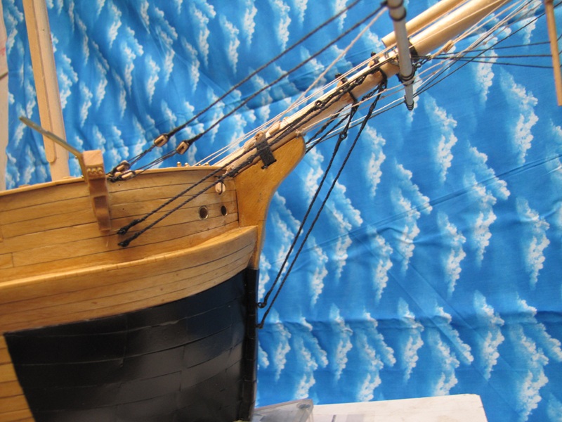
Bowsprit, jibboom and flying jibboom and their rigging.
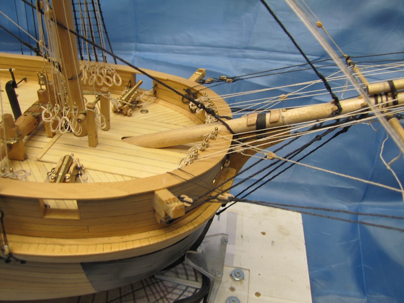
The fore deck and bowsprit. There are two things
shown here that I got from a sketch and notes recorded from
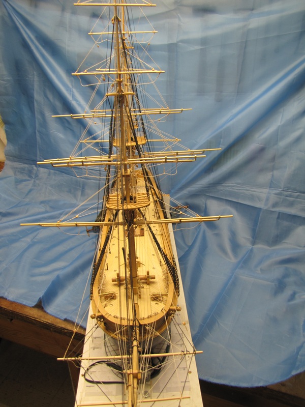
View from forward. March 23, 2026 The final details have been installed making the model complete.
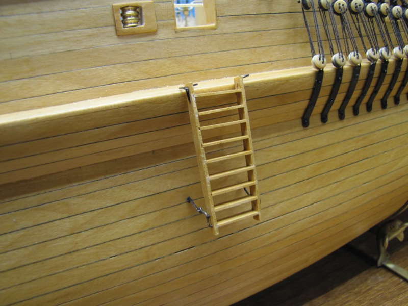
The boarding ladder on the port side. This ladder could be removed and stowed when not in use.
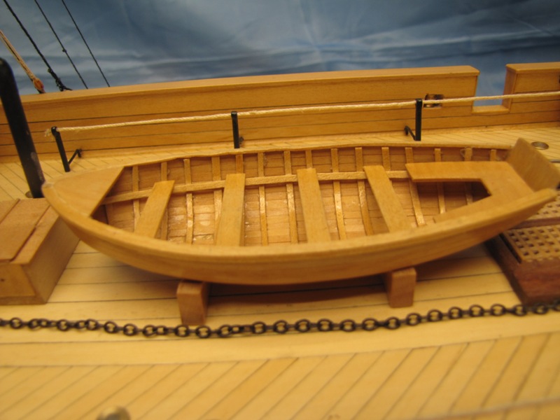
A ship's boat stowed on the upper deck.
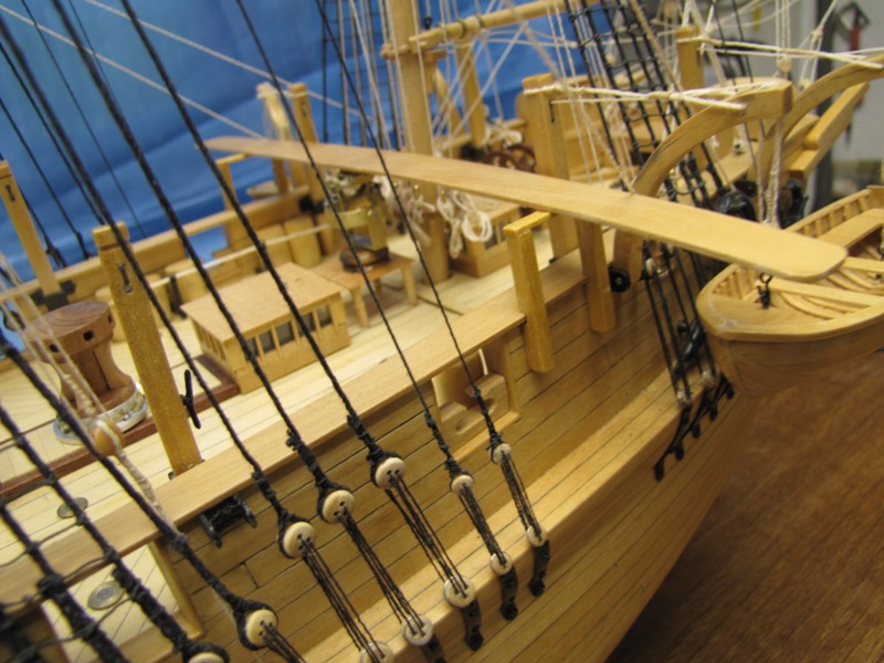
The conning or ice plank. Below it is the azimuth compass on it's table.
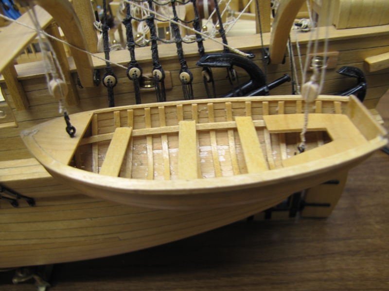
A ship's boat suspended from davit's at the side of the
ship near the stern. There is another one on the
Brass beams used to support the sails were added.
The one on the cathead is a bumpkin. It supports the
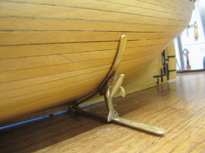
The cradles supporting the model.
|